
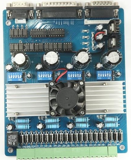
Hello, I have one of those eBay boards, a stepper motor driver for 4 motors, manufactured by the chinese www.huy68.com, it uses the dual full bridge chip Toshiba TB6560AHQ, that is able to supply 3.5A @ 40Vdc to the motors.
The board contains a single long heatsink over the chips, with a single 40mm 12Vdc fan, that runs at full speed all the time, nosy and low air flow, as usual for those cheap $1 fans.
Also, the fan is powered by the 12Vdc regulator on board. The fan consumes from 100 to 120mA, it seems small, but if the user feeds the board with the recommended 24Vdc or higher, the 12Vdc regulator (LM7812) will dissipate the extra voltage and current, from 1 to 1.5W just to feed the fan, what is power and heat wasted.
Because of that, the LM7812 regulator gets unnecessarily warm.
Also, this 12Vdc regulator, feeds power to the +5V regulador, the LM7805, that supplies the logic voltage to the TB6560AHQ chips, it also consumes some power, that of course comes through the LM7812 regulator, heating it even more.
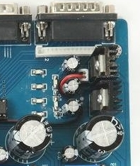
The LM7812 is installed in a single black small heatsink, that may get really hot under heavy use. You can see both black heatsinks at the picture on the right, with both, the LM7805 and LM7812 regulators. The red and black wire in the connector is the wires that feed the fan with +12Vdc.
So, initially I cut one wire of the fan and inserted 6 series 1N4007 diodes, to drop the voltage to the fan from 12V to around 8Vdc, this reduced the fan speed and the power consumed, but it was not enough.

Even so, I produced a air flow duct made with ticker paper (business cards) in a way to guide the air pushed by the fan to the sides of the large heatsink, and at the back side I made the duct to turn left and carry the air over the LM7805 and LM7812 heatsinks. You could feel the cool air flowing over the 7805 and 7812, It helped somehow to keep the regulators cooler than usual.
But that is a ugly and not so nice solution.
Then I thought to move the LM7812 regulator to the same large heatsink, by the way, the large heatsink has the fan cooling thing off. Then I removed the LM7812 from the solder pads, soldered three long tick wires (red in the picture) and moved the LM7812 to between two fins of the large aluminum radiator.
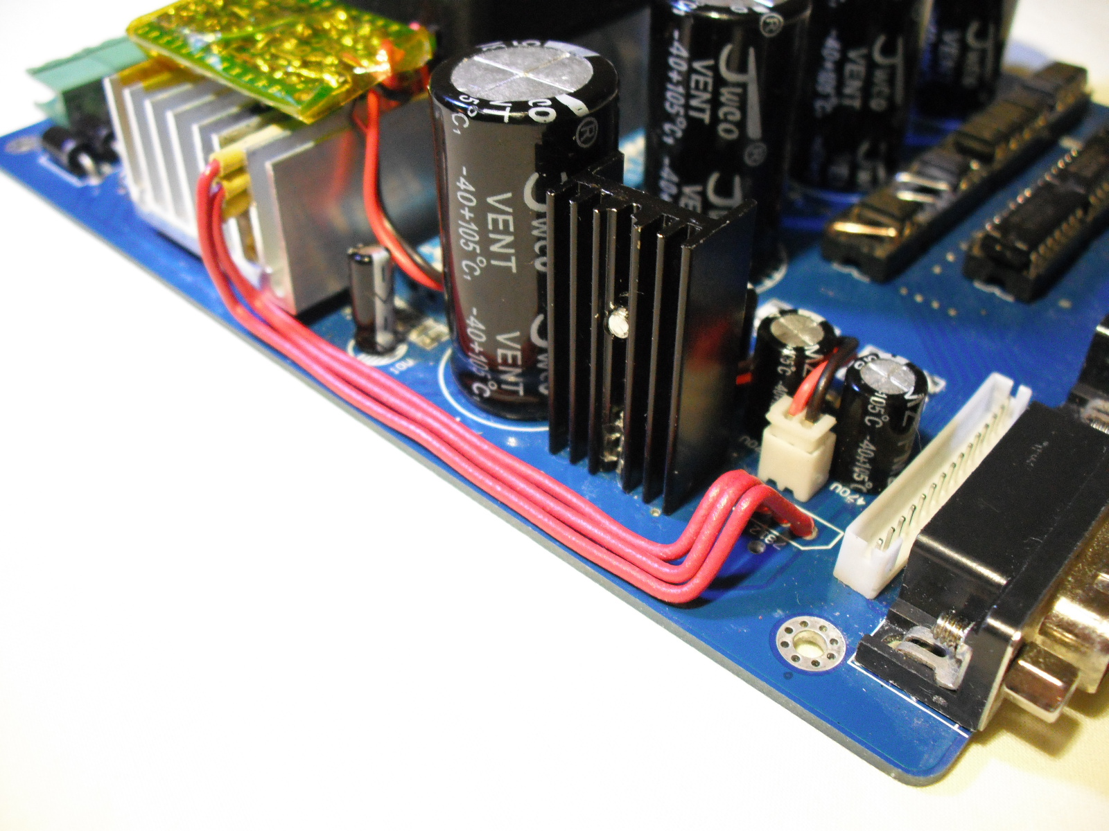 I used a little of the white thermal paste and just inserted the LM7812 between the fins. It was needed to little pry open the fins with a screwdriver so the LM7812 could enter there. There was no need for screw the regulator, the tied position between the fins are enough to hold it in there forever. As the fins were forced open, the back side of the LM7812 with the thermal paste touched nicely the fin, the front side (epoxy) got not so good contact, but it doesn’t matter. Thermal transfer is better than in the original position on the board.
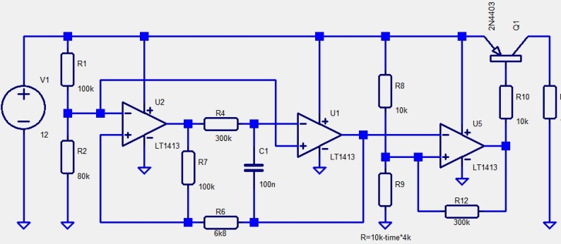
Okay, the LM7812 problem is fixed, now about the fan speed. I though to use one of two approaches, first, use a simple three op-amp circuit, the first generating a square wave, the second using such square wave to charge and discharge a capacitor and producing a triangle waveform, and the third, to compare such the voltage of the triangle wave with a voltage divided by a NTC (negative temperature coefficient) resistor, measuring the temperature of the heatsink. The triangle waveform rides from 5 to 5.8Vdc.
The voltage divider between the NTC and the 10k resistor, creates around 6Vdc when in 75 degrees Fahrenheit. As the temperature increases in the heatsink, the NTC drops its resistance, and the voltage in the divider also comes down, going deep into the range of the triangle waveform. The third op-amp will sense it and generate a digital pulse at its output. The width of the pulse is proportional of how deep the NTC voltage is among in middle of the triangle waveform voltage. As the output of this op-amp drives a transistor and the transistor feeds the fan, as wider is this pulse, the faster runs the fan.
Around 90°F the NTC voltage is around 4.8Vdc, lower that the bottom part of the triangle waveform voltage, so the output of the third op-amp will be steady, applying full power to the fan, that will refrigerate the heatsink and will keep it a little warm between 75 and 80°F.
If the heatsink cools down below 75°F the fan stops completely, saving energy and noise. This idea is nice, but it uses 9 resistors on board, requires some adjustments for the temperatures and it is not exactly high-tech.
Below is the schematics for the analog solution, it works VERY WELL. I developed it in the Linear Technology CAD simullator (LTspiceIV), then assembled it in a protoboard for testing purposes. The two op-amps to the left generates a square then triangle shaped waveform, its ramp voltage is then compared against a fixed voltage at the third op-amp. This “fixed-voltage”, is dependent of temperature, since it comes from a voltage divider between a fixed resistor and a NTC. The result of such comparison drives a PNP transistor that feeds the fan. If the NTC is below certain temperature, the triangle never reaches such voltage and the third op-amp never triggers the PNP, the fan stay stopped. As the temperature in the NTC goes higher, the voltage at the + pin of the third op-amp goes lower, now matching some point of the triangle at the – pin, driving the PNP and the fan. The trigger temperature is defined by the selection of the NTC and the resistor on top of it.
But I had another idea.
Dispite the analog solution above working very well, I always seek another solution using a tinny microcontroller, sometimes is possible, sometimes not. Whenever possible and using less components, and possible less problems, I try to develop and test it.
To be small, I thought about the Atmel AtTiny13, saving parts and several resistors. With the AtTiny13, I only use 2 resistors, one to produce the voltage divider with the NTC, and another to limit the current from the AtTiny13 to the base of the power transmistor that feeds the fan. Of course, the solution using the AtTiny requires 5V for it, and I have only 12V on the fan wires. The solution is to use a small LM7805 close to the AtTiny13, the LM78L05, a TO92 package, enough small to not cause any harm to the idea. Okay, the driver board has +5V, but it would be another wire coming to this fan control board, and I want it as clean as possible, having several 78L05 in the drawer, why not?
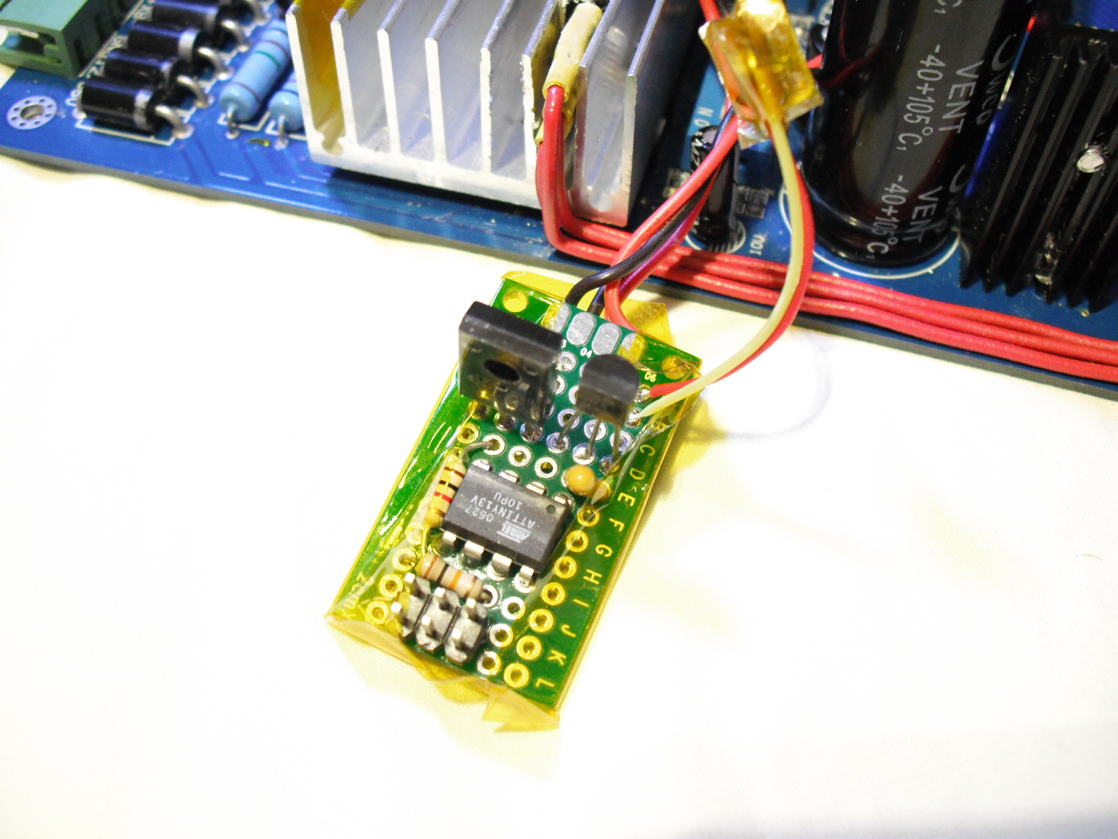
At the left you can see the small prototype PCI with the AtTiny13, 6 pins ISD for reprograming it, two resistors, a capacitor, the 78L05 regulator, at the left side the BDxxx transistor, and at the right side (yellow and red wires) is the NTC (protected with Kepton tape).
So now the 10k resistor and the NTC have the center connected to one of the ADC (Analog to Digital Converter) onboard of the AtTiny. It has ADC mux inputs, I used just one. The idea here is to write a simple AVR assembly program that reads the ADC and use the onboard Timer/Counter function as PWM to generate the pulses that goes to the power transistor feeding the fan. The code reads the ADC, and while inside a certain range of values, turn on the PWM, with different widths according to the values read from the ADC. Now this is programmable, I can setup whatever I want, different from the 3 op-amps idea above. I can even define the start of the PWM with a certain width in the pulse, so the fan will effectively “start to run” slowly but will start. The solution with the 3 op-amps can do something like that, using a positive feedback to the last op-amp, but the final result is somehow not so good.
So, I used the AtTiny13 solution, and the result is as in the pictures.
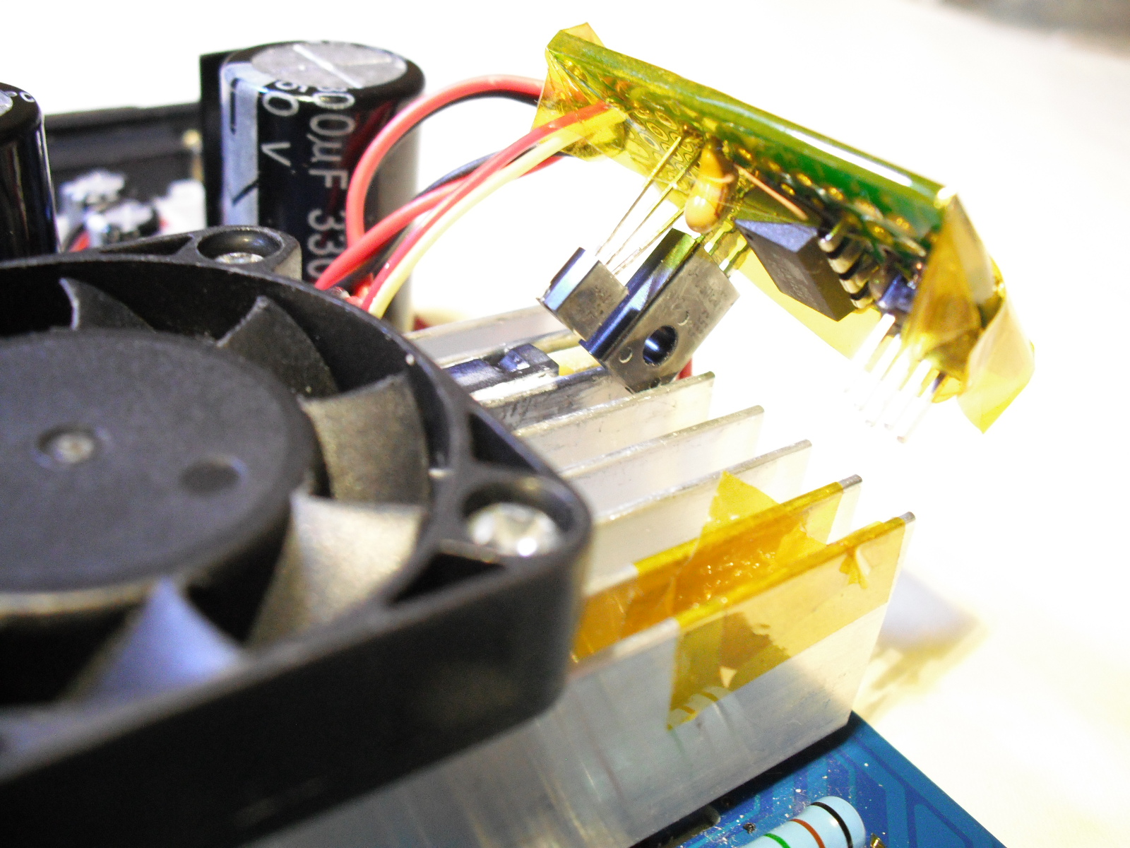
The left picture shows the small prototype board being installed. Note the body of the BDxxx transistor going in between the fins of the heatsink, along with the TO92 body of the 78L05. Both enter also tied fins, needing a little pry with a screwdriver. Both transistores goes entirely down between those two fins, with no electric contact at all.
This is good, the BDxxx is able to transfer any heat to the heatsink, and also holds the small board in place, no screw, nothing.
The yellow Kepton tape on the heatsink is to isolate the ISP pins on board to electrically short to the heatsink aluminum. The body of the AtTiny13 serves as a spacer between the fins and the circuit board.
Of course, I used a BDxxx transistor to drive the fan. I tested nicely using a small TO92 2N4103 transistor, and it worked well, but I was afraid of the future unforseen situations, then I changed the driver transistor to a BDxxx unit, capable to drive a larger fan, dissipating more heat if necessary.
The BDxxx transistor was soldered in the small board in a way that when the board is over the large heatsink, the BDxxx body goes inside two fins, also refrigerating as necessary. See the pictures.
Next step is to produce a professional small Printed Circuit Board, that will hold also the LM7812 and LM7805 regulators and put is available for sale at http://www.urkit.com, for a low price, so you can do this modification to your stepper motor driver board.
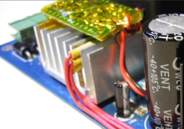
At the right you can see the board over the heatsink. A necessary installation screw will hold the board to the heatsink.
For a prototype it is enough
Wagner.