|
|
|||||||
|
|
||||||||
|
|
|||||||
|
|
||||||||


User Manual Printing Version | User Manual Screen Version | Epromer Software | What is Memory? | Sales Webpage
|
EPROMER5
- UST Research Inc. TESTING
The tests cover all the functions of the Epromer5, from voltage levels, pulses width, response time, VPP recovery, chips blank, read, compare and programming, along several other data loop back, and address to data loopback using special sockets and connectors. The PRODUCTION test includes a 60�C temperature chamber data loopback tests. The INVENTORY tests include a vibration test, added to the transportation vibration, locate any cold soldering issues. The OWBS tests make sure not a single failure will be delivered to the customer. A new test was introduced recently, before stocking each Epromer board is tested during 15 minutes with a fast AVR microcontroller driving it in a full operation simulation with a dummy eprom. All this thousands of tests looped during the 15 minutes period are evaluated and not a single failure is acceptable. The new multiple test bench is able to test 50 units concurently. This ensures you a error free board. Below there is a compilation of cases reported by customers, that we feel important to list here, since most of the cases are just our own lack of information or operation instructions, not a device problem itself. If none of the information below help you to solve your situation, please contact our technical support to further help. Also read the Epromer5N windows software help section, as well download and read the Epromer5 PDF file from the download webpage. Make sure you are always using the latest Epromer5N software version. Just donwload the latest updated version and replace the existent at your computer. If you want to read and understand more about Eproms, EEproms and Flash units, please read our webpage about it; memory.htm. AC
POWER ADAPTER EPROMER
PROTECTIVE CASE EPROMER
WINDOWS SOFTWARE If you need some basic information about memories and packages, please read our small webpage about it. Steve
Banners The most common causes for Epromer5 not being working are:
|
|
GREEN LED OFF |
Make sure the Power DC Adapter is plugged at the wall power outlet. Make sure the power outlet is energized (110VAC). Make sure the DC Power Adapter is plugged at the Epromer5 power connector input jack. |
|
RED LED OFF |
The RED LED usually stays OFF all the time. It only blinks in special situations as for example, during programming. THE RED LED can stays continuous ON right after connect power to the board, it only means the board did not receive any command from the Epromer5N software yet. You should NEVER insert or remove any chip at the socket while the RED LED is ON. If even after run the Epromer software, clicking TEST PORT button, the RED LED stays on, please read the 4700pF capacitor information below. |
|
BLANK
EPROMS |
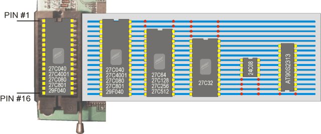
When you BLANK CHECK a "for sure blank eprom" and it returns as not blank, you may have installed the chip in the ZIF Socket in a wrong orientation or position. Check
the DEVICE ORIENTATION at the picture below. |
|
READ -
VERIFY |
If you READ and then VERIFY a chip, it SHOULD MATCH, since at the READ it copies the contents of the chip to the code-buffer, and then when VERIFYING, it will compare the recent read data with the actual chip contents. If it DOES NOT match, it means the unit is reading bad data from the chip, so it will not compare match.
|
|
READ PROBLEMS. |
If you are READING a "for sure" programmed chip and its contents return bad, as full "FF's" or not coerent;
|
|
PROGRAMMING ERROR |
Several
factors can generate this error. List of the most common cases:
|
|
|
|
|
CHECK VPP VOLTAGE |
It requires a VOLTMETER, able to measure from up to 30Vdc and a piece of small gauge wire (small paper clip will do).
|
|
READ TEST PROCEDURE |
The READ TEST procedure DOES NOT USE any chip at the socket, instead uses the jumper between pins #16 and #17 (as in the above picture). This test assures you the whole system, Epromer board and software are able to read the socket. Follows the procedure:
If the
above test procedure runs ok, the whole system read operation is
fully operational, and any read failure should be attributed to
a failling chip. |
|
TEST PORT BUTTON |
The EPROMER Windows software can drive the EPROMER4, EPROMER5 or the new EPROMER6 model boards. The boards are not the same and use different software routines. The first time you run the EPROMER windows software, it looks for an "INI" file, that would contain all the setup information, such as EPROMER model number and LPT port where it is installed. If this file is not located, the EPROMER software launches the TEST PORT function automatically. This function broadcasts commands to all LPT ports, in attempt to recognize an EPROMER board answers. When found, the answer also identifies the EPROMER board model, so the software creates the INI file and will use that setup from that moment on. In case you have both EPROMER models, you always need to force this TEST PORT function to update the "INI" file, by pressing TEST PORT button. If you try to use a wrong setup, you will experience several errors.
Whenever you downloada new version of EPROMER windows software, or something seems to be not quite right, it is extremely important to click the TEST PORT button, so a new "INI" file will be created. It is always possible that the new software version generates and uses the "INI" file in different way. Also,
after a new version download, make sure your personal SETUPs still
valid and correct. The inclusion of new devices in the new
software version, can mess up with your personal SETUPs. This
can happens because each DEVICE is represented by a sequential number
into the software, also stored in your personal setups. When a new
device is inserted in the list, all the above chips will have their
ID's shifted and your personal setups will be wrong. Check them
and correct if necessary. |
|
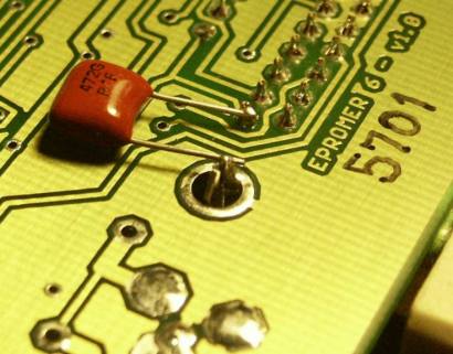
An
impedance issue was found between the Epromer board and the parallel
port. It is related to some strange combinations of windows platform,
the motherboard (or parallel adapter cards) and computer speeds.
Even being rare to happens it was already reported by few
customers. WAGNER
LIPNHARSKI - EP-CAP-FIX Starting March/2004, all new boards shipped will have this capacitor installed as prevention. In most cases this capacitor is not necessary and will not cause any problem being there.
There is no way to test if your board needs or not the capacitor. If you have problems to program AM29F040 flash units, then probably the capacitor is the solution. Steve Banners - Technical Support - March/2004 |
|
|
CHIP ORIENTATION
|
|
Last update: January 26, 2003
UST
Research Inc. - Orlando Florida
Technical Support Group